Measuring High-Frequency, Common-Mode Current, Voltage, and Impedance (Part I)

Get valuable resources straight to your inbox - sent out once per month
We value your privacy
Introduction
To obtain an accurate EMI analysis when modeling power electronics, it is crucial to measure the impedance on the noise source and propagation path. For radiated EMI, the corresponding frequency band is typically between 30MHz and 1GHz. Due to the high frequency, it can be difficult to measure parameters such as voltage, current, and impedance.
This article is the first part of a three-part series discussing measurement methods for high-frequency, common-mode (CM) current, voltage, and impedance using a flyback converter. These methods are credited to Dr. Wang Shuo, a University of Florida professor and IEEE fellow.
Part I will introduce a radiated EMI model and measure high-frequency, CM current in a flyback converter topology. Part II will address measurement errors for CM current, and then explore how to measure CM impedance in flyback converters. Finally, Part III will discuss the switching noise source effect, measure the equivalent voltage source, and verify the proposed measurement methods.
Basic Principles of Radiated EMI
When a converter operates in a circuit, the dV/dt nodes and dl/dt loops generate high frequencies. A high-frequency CM voltage (VA) is generated between the input and output lines. Note that these lines are equivalent to a pair of dipole antennas. VA generates a high-frequency, CM current (IA) on the input and output lines, which radiates energy outward in the form of an electromagnetic field.
According the Tevenin’s theorem, a converter’s radiation model can be simplified to its voltage source and the impedance in series (see Figure 1).
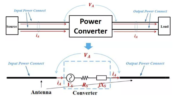
Figure 1: Converter’s Radiated EMI Model
To build an accurate radiation model and predict radiated EMI, designers must know the model’s key parameters, including the noise source (VS), excitation voltage (VA), excitation current (IA), source impedance (RS), and the antenna impedance (XS).
Using Antenna Impedance to Analyze Radiated EMI
Figure 2 shows a model of the antenna's energy, which consists of three parts. The first part is converted between the two poles and does not radiate outward. The impedance corresponding to this reactive power can be expressed by jXA. The second part represents the emitted energy (RR), and the last part is the resistance that represents the cable’s power loss (RL).
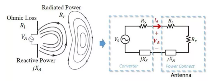
Figure 2: Equivalent Model of Antenna Impedance
The overall radiated EMI model is obtained after considering the antenna's impedance. By transforming an electromagnetic field model into a circuit model, engineers can effectively analyze EMI.
Measuring Radiated EMI
To measure radiated EMI, determine the intensity of the electromagnetic field generated by the converter from a certain distance away. Consider the electric field from the distance of the converter (r). The maximum electric field intensity (EMAX) can be calculated with Equation (1):
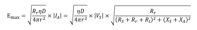
Where VS represents the noise source, η is the wave impedance, and D is the directionality. D indicates the maximum power density ratio in the direction of the spherical surface’s average power density (with a radius of r, which can be obtained by measurement or simulation).
To predict the final radiation result, this article series will use a flyback converter to find the accurate noise voltage, CM current, and impedance.
Measuring High-Frequency, CM Current in Flyback Converters
Figure 3 shows the flyback converter's topology and CM current path.
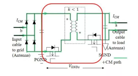
Figure 3: Flyback Converter Circuit
On the CM path, the primary side includes CM filters, rectifier bridges, and electrolytic capacitors. The CM current flows through the transformer to the secondary side and output line. Note that the rectifier bridge’s junction capacitance has minimal impedance at high frequencies, which could be considered a short circuit. In addition, the impedance of the input and output electrolytic capacitors is also minimal; at high frequencies, it could be considered a short circuit. Therefore, the input line and output line should be considered to be two nodes in the circuit (noted as “a” and “b” in Figure 3).
Figure 4 shows the radiation model. In this model, VCM is the equivalent noise voltage source, which is discussed in further detail in Part III. ZCMTRANS is the transformer’s CM impedance, while ZCMCONV is the CM impedance of other components on the loop, such as the PCB traces and filters. The CM current (ICM) is measured as the current that goes the same direction on both the input and output lines.
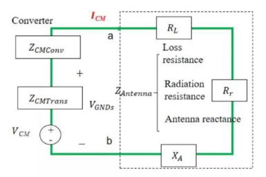
Figure 4: Radiation Model of Flyback Converter
Figure 5 shows the traditional method to measure ICM. The high-frequency current clamp can simultaneously clamp the input’s live and neutral wires. In addition, this clamp can obtain the CM current spectrum when it is connected to the spectrum analyzer via a coaxial line.
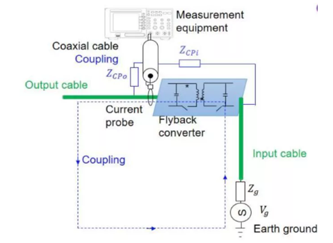
Figure 5: Traditional Test Method of CM Current
However, the traditional method is not always accurate since coupling occurs between the converter and the coaxial line. This includes the electric field coupling between the dV/dt node and the coaxial line, as well as the magnetic field coupling between the dl/dt loop and the coaxial line, which is located between the converter and the ground. Additional measurement errors are addressed in Part II.
Conclusion
This article reviewed the basic principles of radiated EMI, discussed the key parameters of the radiation model (i.e. the antenna impedance), and a described a method to calculate radiated EMI. Then this article examined the traditional method to measure ICM in a flyback converter topology.
Part II will address sources of interference and error when measuring parameters, in addition to methods for calculating CM impedance. Part III will consider the switching noise source effect and the equivalent voltage source, before verifying the proposed measurement methods.
_______________________
Did you find this interesting? Get valuable resources straight to your inbox - sent out once per month!
Technical Forum
 Latest activity a month ago
 2 Comments
Latest activity 2 months ago
2 Comments
Latest activity 2 months ago
2 Comments
2 Comments
Latest activity 2 months ago
2 Comments
Latest activity 2 months ago
2 Comments
Log in to your account
Create New Account