DC Fast Charging System: Maximizing Power Density with an LLC Transformer Driver

Get valuable resources straight to your inbox - sent out once per month
We value your privacy
Introduction
As the world strives for carbon neutrality, electric vehicles (EVs) are rapidly taking market share from internal combustion engine vehicles. However, one of the issues with electric vehicles is range anxiety, as customers are unsure of how long they will be able to drive without the car needing to be charged. To combat this, governments around the world are massively investing in charging infrastructure.
Types of Charging Stations
Several types of charging stations are being used today, from Level 1/Level 2 (L1/L2) charging stations to DC fast-charging (DCFC) stations that can provide up to 400kW of power (see Figure 1).

Figure 1: Electric Car Charging Stations
These charging stations are described in greater detail below.
- L1/L2: These stations provide AC power to charge an electrical vehicle, and generally take 8+ hours to fully charge an EV. L1 chargers charge at 3kW or less (meaning a car can be charged to drive 2 to 10 miles per hour of charging), while L2 chargers are rated for 3kW to19kW (10 to 25 miles of range per hour) of AC power.
- DCFC: This charging station can charge an EV battery from 20% to 80% within 40 minutes, depending on the power rating (50kW to 400kW) of the charging station itself and the maximum power that the vehicle can be charged at.
When charging at home or at work, L1/L2 stations are sufficient. However, DCFC and supercharger stations are necessary for people who cannot charge over longer periods of time, such as when a driver is on a longer trip where the battery’s full capacity is utilized.
Figure 2 shows the different types of connectors that are used globally for both L1/L2 AC charging and DCFC. While DCFC is convenient and quickly replenishes energy, the high charging rate degrades EV batteries more quickly than AC charging. L1/L2 charging utilizes the on-board charger in an EV to convert the AC power into DC power to charge the battery. On the other hand, DCFC stations house all of the power electronics to convert the AC power from the grid into DC power, which can be used to directly charge a vehicle battery.
Note that Tesla uses a proprietary plug for their superchargers in all markets except for Europe, where Tesla also offers CCS2 connectors.
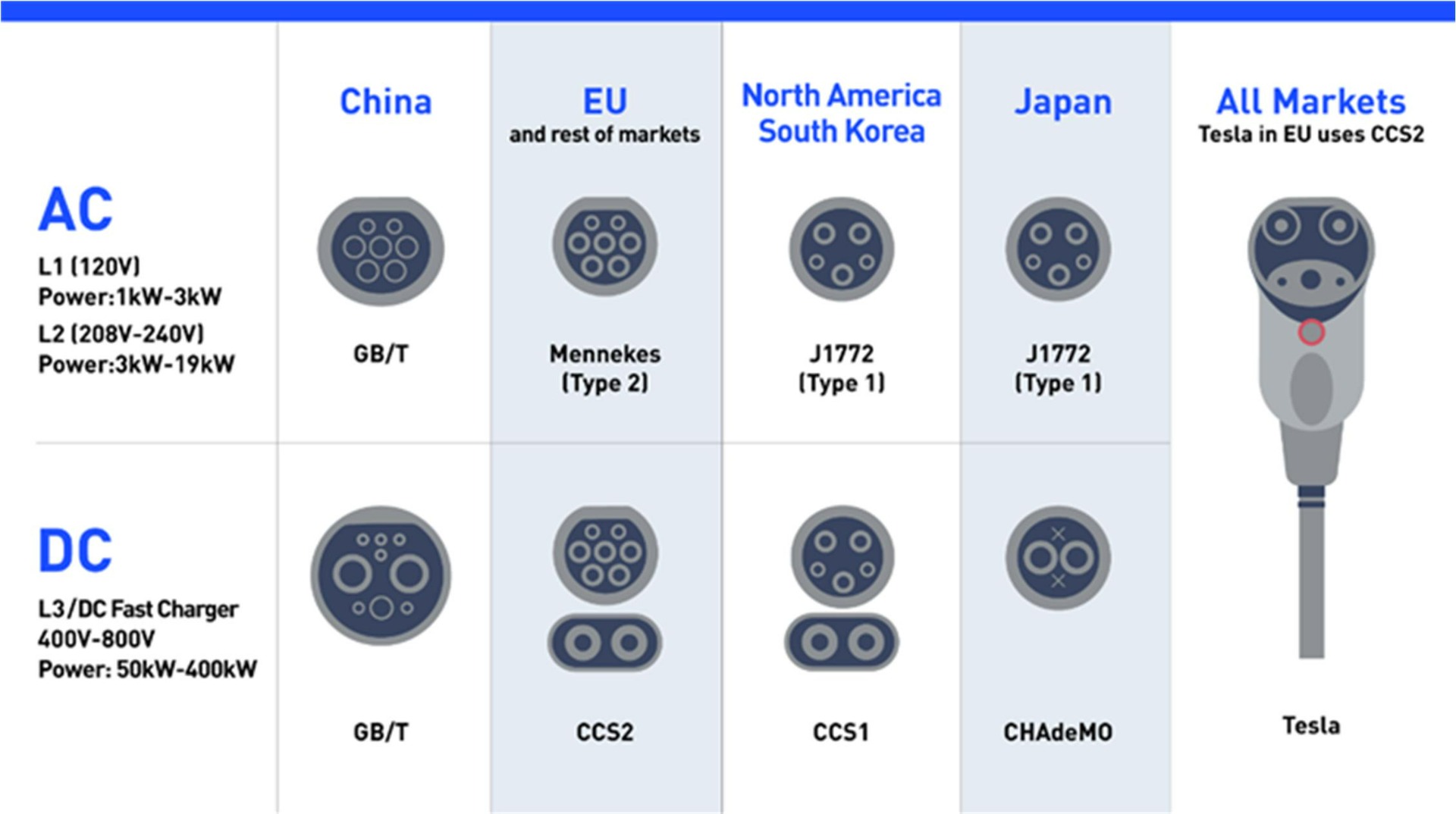
Figure 2: Global Chargers Connectors
Figure 3 shows a typical DC fast-charging station block diagram to convert a 3-phase AC voltage into a 250V to 800V DC voltage to charge electric vehicles. A DCFC station typically contains several of these subunits, each ranging from 30kW to 75kW. This diagram exhibits many of the solutions that can drive DC fast charging stations, including isolated gate drivers, isolated power modules, transformer driver bias, and digital isolator solutions with an integrated power supply.
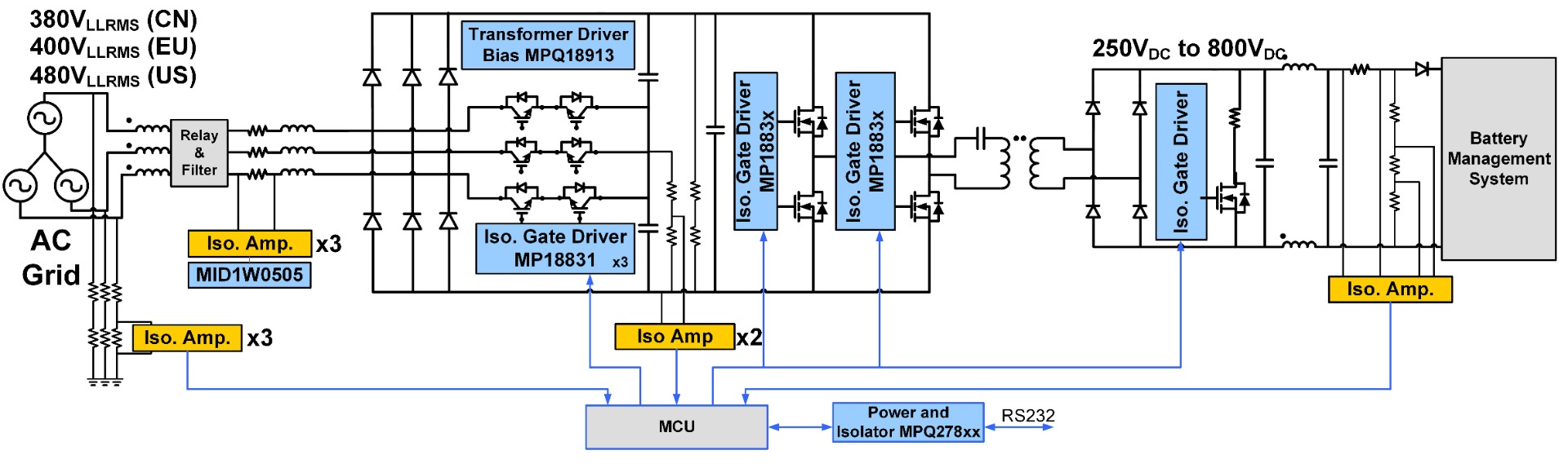
Figure 3: Block Diagram of a DCFC Subunit
Figure 3 shows that the DCFC system is generally comprised of two conversion stages. The first stage is a power factor correction (PFC) stage, which converts the AC voltage from the power grid into an intermediate DC voltage bus between 800V and 1300V. Three-phase, 3-level rectifier/inverter topology is commonly used for the PFC stage. This particular topology refers to a three-level converter that can interface with a 3-phase power grid.
At the second stage (also called the DC/DC stage), an isolated DC/DC converter converts the intermediate DC voltage to the target voltage that is specific to the battery being charged. LLC and phase-shift full-bridge converters are common topology choices for the DC/DC stage.
Some of the challenges for designing high-power charging stations are maximizing power density, reducing cost, and reducing size. One industry-wide method to increase efficiency is to replace semiconductor MOSFETs/IGBTs with silicon carbide (SiC) FETs. This is particularly important since DCFC stations have increased in power from 50kW to more than 400kW.
Due to the high-voltage and high-power nature of DCFC systems, isolated devices are required to protect users and low-voltage control circuitry from the potential hazards and disturbances that could originate from the high-voltage power conversion circuits. Additional components can be implemented to reduce the risk of hazards:
- Isolated gate drivers for SiC MOSFETs and IGBTs, such as the MP18831 and MP18851
- Digital signal isolators, such as the MPQ27811 and MP27631
- Isolated current-sensing and voltage-sensing devices, such as the MCS1806 and MCS1803
Note that isolated gate drivers require an isolated bias supply for power, and that the gate drive power supplies must be able to withstand high isolation voltages. At minimum, the gate driver power supplies must be able to withstand the intermediate DC bus voltage, and must offer low isolation capacitance to minimize disturbances from the high-voltage side to the low-voltage side.
Related Content
-
VIDEO
Gate Driving for High-Voltage Converters: Understanding Isolated Gate Drivers
Learn more about the MP188x1 series
-
ARTICLE
Building Power Systems with the MP188xx Isolated Gate Driver Series
Explore MPS's isolation products
-
VIDEO

Isolated, High-Voltage ±5A to ±50A Current Sensors
Learn more about the MCS18xx sensor family
-
APPLICATION NOTE
Automotive
See how our automotive power management can improve your design
Designing an Isolated Power Supply for Gate Drivers
The MPQ18913 is a transformer driver for isolated bias supplies. This device can work with SiC FETs as an isolated bias for SiC gate drivers. Flyback topology is often used for isolated power supplies to provide an isolated 18V/-4V output that drives the SiC FET. Figure 4 shows a typical application circuit implemented with the MPQ18913 to achieve a 18V/-4V output. The number of outputs can be configured based on the transformer used and the output voltage can be altered via the turns ratio.
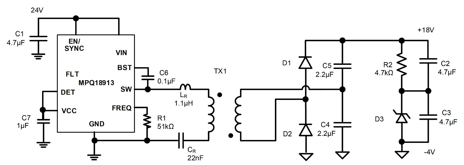
Figure 4: MPQ18913 Application Circuit
The MPQ18913 can be used as an LLC converter, which is the most efficient topology for isolated gate drive power supplies (see Figure 5). These converters use a resonant LLC tank, which has a magnetizing inductor for energy transfer, as well as an additional capacitor and inductor that make the tank resonate at a certain frequency. The converter uses this resonance to achieve soft switching and ensure highly efficient power conversion. The main benefit of LLC converters is that the leakage inductance created by the transformer can be used as the resonant inductor in the tank. This eliminates the voltage spike induced by the leakage inductance, and improves efficiency compared to flyback topologies.
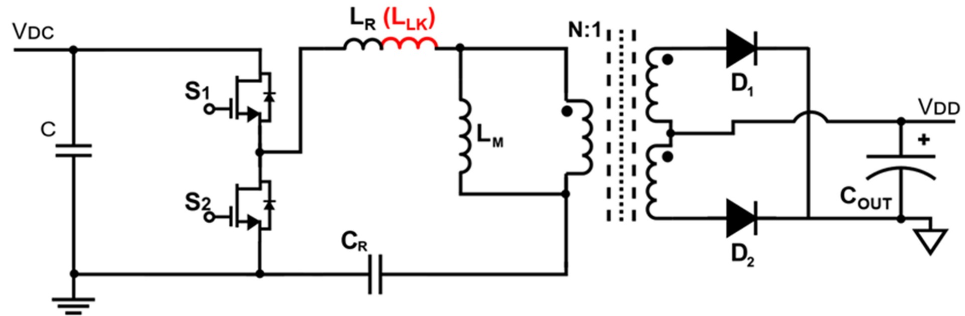
Figure 5: LLC Topology
Using the MPQ18913 as an example, the LLC resonant topology offers several notable advantages compared to a typical PSR flyback topology. One such advantage is that LLC resonant topology reduces the solution size due to the switching frequency (fSW), which can reach up to 10MHz, whereas with flyback topology, fSW stays below 400kHz. This results in a total solution size that is 40% smaller than a flyback application using a similar power level. Another major advantage of LLC resonant topologies is the fact that the isolation voltage can easily reach up to 5kV. Traditional flyback solutions only reach 1.5kV, therefore meeting more stringent isolation voltage requirements.
Table 1 compares LLC resonant topology to flyback topology.
Table 1: LLC Resonant Topology vs. Flyback Topology
| Parameter | LLC Resonant Topology | PSR Flyback Topology | Benefit |
| Switching frequency (fSW) | High (up to 10MHz) | Low (<400kHz) | High frequency enables much smaller solution size |
| Transformer size | 13µH (11mmx6mm) | 30µH (10mmx10mm) | |
| Leakage inductance | Utilizes leakage inductance as part of the resonant tank | Leakage inductance reduces performance | In LLC, leakage inductance enables higher efficiency and prevents voltage spikes |
| Isolation voltage | High (up to 5kV) | Low (1.5kV) | LLC enables higher isolation voltage to increase safety |
| Isolation capacitance | Low (6pF) | High (Up to 25pF) | Up to 40% reduction in solution size and 20% fewer component count |
| Package size | 2mmx2.5mm | 4mmx4mm | |
| Diodes (including Zener diode) | 3 | 6 | |
| Solution size | 109mm2 | 180mm2 | |
| BOM components | 21 components | 26 components |
Conclusion
High-frequency LLC power supplies are typically more difficult to implement and optimize in designs than low-frequency converters, but devices like the MPQ18913 simplify LLC power supplies with features including automatic resonant frequency detection and integrated transistors. In addition, LLC resonant topologies reduce solution size, which increases power density for high-power charging stations such as those used for charging electric vehicles. As electric charging infrastructure continues to improve, look out for the MPQ18913 being used to bias SiC FETs in high-power charging applications, as well as automotive applications such as on-board chargers, traction inverters, and DC/DC converters.
_______________________
Did you find this interesting? Get valuable resources straight to your inbox - sent out once per month!
Technical Forum
 Latest activity 3 days ago
 2 Comments
Latest activity 3 days ago
2 Comments
Latest activity 4 days ago
6 Comments
2 Comments
Latest activity 3 days ago
2 Comments
Latest activity 4 days ago
6 Comments
Log in to your account
Create New Account