Designing an Active-Clamp Forward Converter for PoE-bt Applications (Part I)

Get valuable resources straight to your inbox - sent out once per month
We value your privacy
Introduction
When compared to traditional AC power supply modes, power over Ethernet (PoE) power supplies can simultaneously supply power and transmit data through an existing Ethernet cable. By integrating the power supply and data cables, PoE applications are cost-effective and provide flexible installation. PoE solutions are rapidly growing in popularity across multiple industries as applications continue to demand more power.
This article is the first part of a two-part series exploring how to design an active-clamp forward controller for PoE-bt applications. Part I will introduce PoE applications, as well as the basics for forward converter topologies and active clamps.
The Development of Power over Ethernet (PoE)
Figure 1 shows how PoE functions have evolved. In 2003, PoE was only capable of providing devices with a maximum power of 13W, which is called the 802.3af protocol. Eventually, 13W was unable to meet the increasing demand for power, so the 802.3at protocol was released in 2009. This protocol improved voltage and current specifications, providing up to 25.5W of power. Most recently, the 802.3bt protocol was released in 2019 to meet the rapid development of PoE applications by providing up to 71W of power.

Figure 1: PoE Evolution
The majority of PoE solutions are comprised of two parts: the powered device (PD) and the power-sourcing equipment (PSE) (see Figure 2). While both the PSE and PD receive power from the AC power source, the PSE behaves like a power source, whereas the PD consumes power. To ensure that the PSE delivers power to the PD, a handshake process is used to protect the PD from damage in case it is connected to PSE devices with an incompatible protocol.
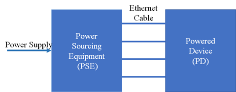
Figure 2: Main Components of PoE
Typical PSE devices include network switches and routers. Typical PD devices consist of IP phones, security cameras, and base stations. MPS provides a comprehensive number of solutions for af, at, and bt protocols. These solutions include the protocol, DC/DC controller, integrated protocol, and power IC, as well as applications at different power levels. For example, the MP80xx series products feature highly integrated DC/DC converters and controllers that are compatible with the af, at, and bt protocols.
Consider the MP6005, a DC/DC controller that supports designs under all current PoE protocols. The MP6005 uses a low-end active-clamp circuit, and can be used with both flyback and forward topologies to transmit power from the PSE.
Topological Comparison
To improve safety and reliability, isolation circuits are often used in PoE applications. Flyback and forward converters typically have isolation circuits that provide power below 100W. Figure 3 shows the common isolation circuits of the basic flyback topology (left) and the basic forward topology (right).
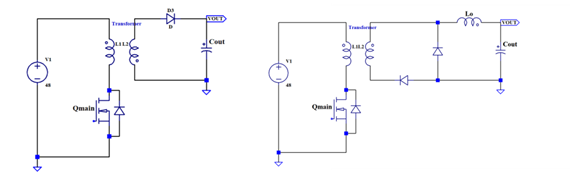
Figure 3: Common Isolation Circuits of Flyback and Forward Converters
When compared to flyback converters, forward converters do not require energy storage during the transformer’s switching process. As a result, there is higher efficiency because there is less current stress on power devices. However, forward converters require more switching devices at higher costs.
Forward converters are well-suited for applications with a low voltage and high output current. At the same time, a primary-side active clamp and a secondary-side synchronous rectification circuit are often added to further improve the forward converter’s efficiency. Table 1 compares the size and costs between active-clamp flyback converters and forward converters.
Table 1: Flyback Converters vs. Forward Converters
| Flyback Converter | Forward Converter | |||
| Component | Size | Cost | Size | Cost |
| Power transformer | Larger | Higher cost | Smaller | Standard cost |
| Output inductor | Smaller | Lower cost | Larger | Standard cost |
| Bias inductor | - | - | Smaller | Lower cost |
| Reset FET | - | - | SOT-23 | Lower cost |
| Synchronous FET | One | Higher cost | Two | Higher cost |
| Output capacitors | More than one | Lower cost | Fewer than two | Lower cost |
Forward Converter Design
Figure 5 shows the topology of a forward converter that is isolated by a transformer, where QMAIN is the main switch, QAUX is the auxiliary switch, QF is the secondary-side freewheeling MOSFET, QR is the secondary-side rectifier MOSFET, and LO is the output inductor.
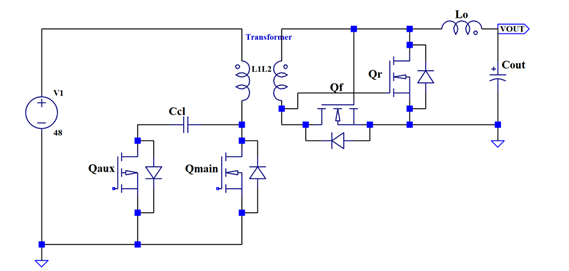
Figure 5: Forward Converter Topology
Active Clamp
Common clamp circuits in isolation circuits include the RCD clamp and the active clamp. In RCD clamp circuits, the energy on the magnetizing inductance (and part of the leakage inductance) dissipates through the resistance in the RCD. This reduces the topology’s overall efficiency. The high-voltage spike on the main MOSFET may not only cause problems with electromagnetic interference (EMI), but can also create difficulties when operating the secondary-side synchronous rectification MOSFET. This issue will be described in greater detail in Part II.
Active-clamp circuits overcome the shortcomings of the RCD clamp circuit. Active clamps not only recover the energy of the magnetizing inductance and leakage inductance, but they also suppress the voltage spike on the main switch MOSFET. The auxiliary switch can also work in soft-switching mode to improve efficiency. An active-clamp circuit can be divided into high-end and low-end components, based on the position of the auxiliary MOSFET. For example, the MP6005 uses a low-end active-clamp circuit.
When the primary-side main MOSFET turns off, the switching voltage is composed of the magnetizing inductance’s reset voltage and the clamping capacitor voltage. A larger-value clamping capacitor corresponds to a lower switching voltage amplitude, lower resonant frequency of the clamping capacitor, and lower magnetizing inductance. Because the bandwidth of the control loop is usually set between one-fifth and one-third of the resonance frequency, the clamp capacitance cannot be too great, or it may affect the control loop’s response speed.
Summary
In this article, we reviewed the evolution and main components of PoE solutions, topological comparisons between flyback and forward converters, and common clamp circuits, including active clamps. Part II will go further in depth and discuss secondary-side synchronous rectification MOSFETs, secondary spike absorption circuits, and efficiency verification processes for PoE-bt applications.
_______________________
Did you find this interesting? Get valuable resources straight to your inbox - sent out once per month!
Technical Forum
 Latest activity 4 days ago
 2 Comments
Latest activity a week ago
2 Comments
Latest activity a month ago
2 Comments
2 Comments
Latest activity a week ago
2 Comments
Latest activity a month ago
2 Comments

Log in to your account
Create New Account